The Bernina 1130 in our house had an issue with not turning on. While working on that problem, I also noticed the light switch wasn’t latching properly. So I took it apart and cleaned it. That’s when my wife told me she’s not using the lights, because it gets so hot she burns her fingers.
There are two 4 W light bulbs (6 V, BA9s socket) on the 1130. They do get insanely hot, and only one of them has a diffusor that protects your fingers from touching the bulb.
I set out to convert the machine to LEDs.
At first, I thought I’d just get BA9s bulbs from China, but waiting several weeks for that seemed less fun. And I have lots of LEDs waiting to be used.
Phase One: The 5 mm and 1206
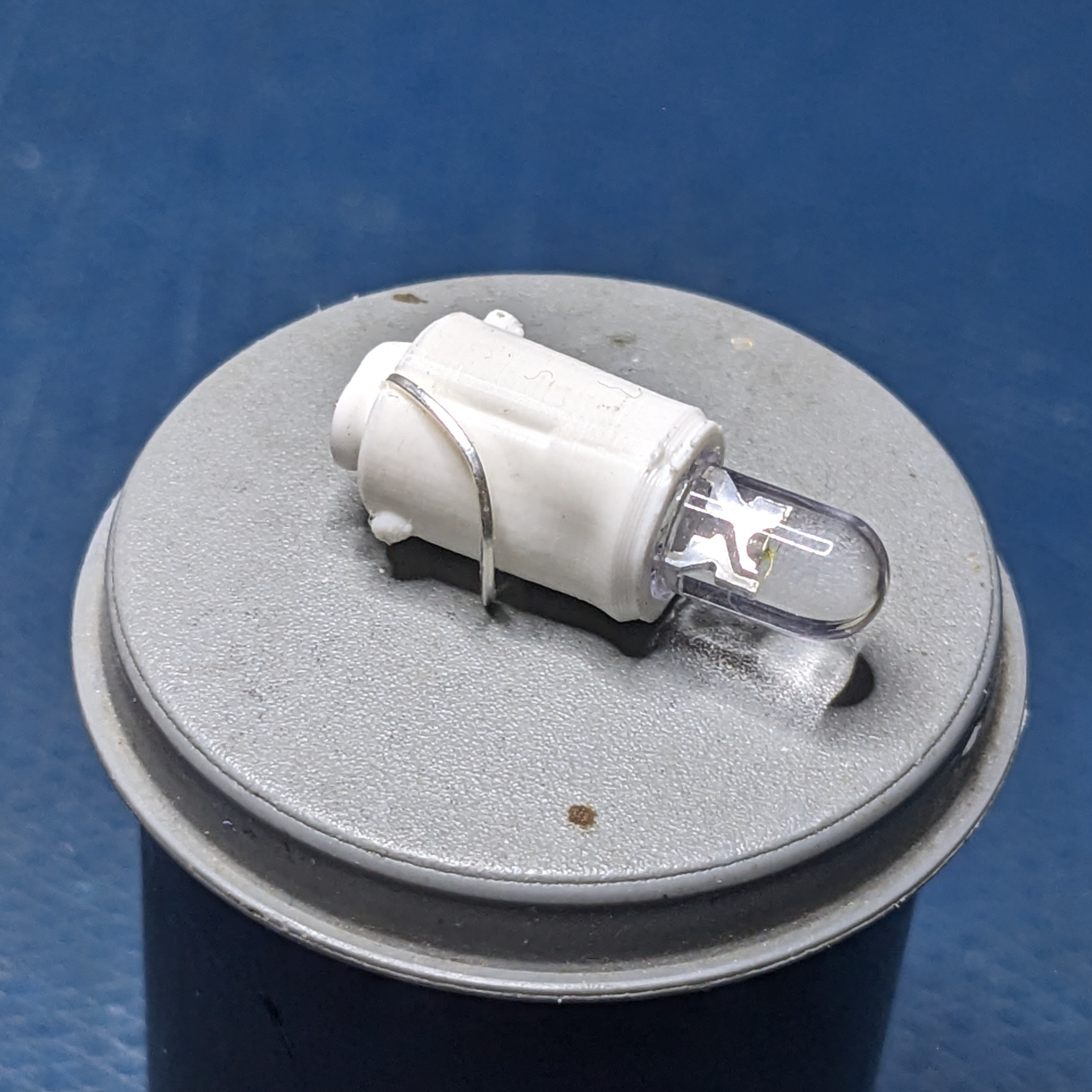
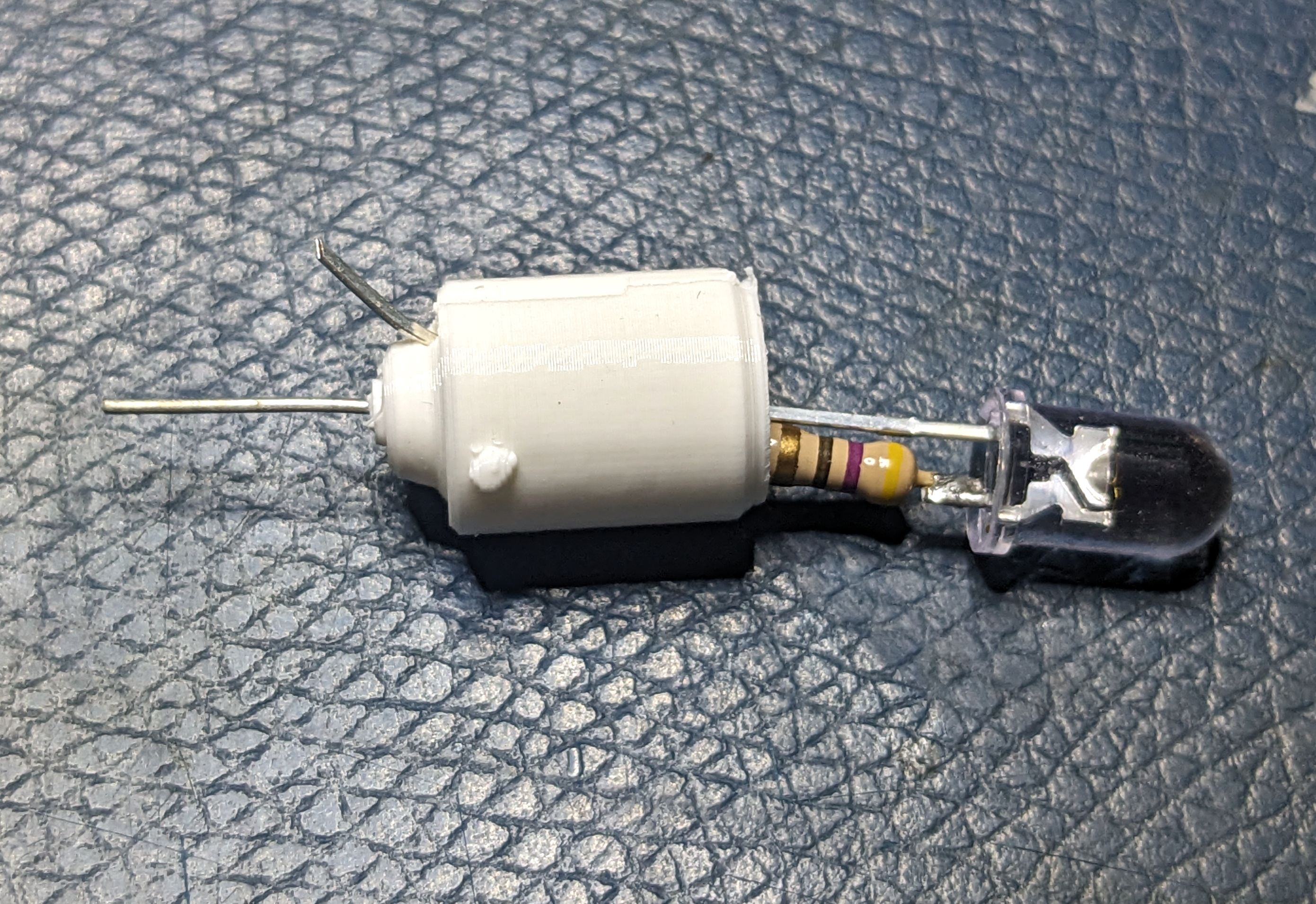
So I designed and 3D-printed a BA9s holder for a 5 mm LED in PLA. This worked, but was getting very hot and eventually blew the machine’s power supply fuse. The PLA body had disformed, and the resistor was burnt. It was only drawing 20 mA from my bench power supply, so I was confused.
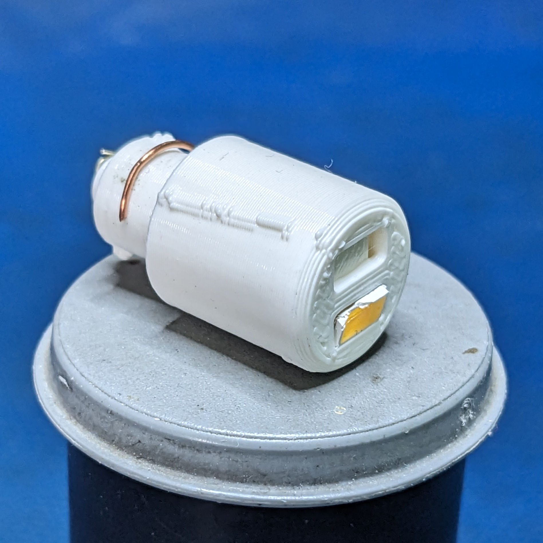
At the same time, the light output was abysmal, it wasn’t worth the power. So I switched the design to some 1206 chips. Now it was so bright, I didn’t even have to install the second chip! Plus the larger light cone was useful for general illumination.
However, this too got really hot and eventually gave up. Something was clearly not working as I had expected. How hard can it be getting an LED to shine? It seems to work with my bench power supply, staying cool and bright, but as long as it goes into the machine, it heats up and things break.
Phase Two: Fixing The Supply
I decided to have a look at the 6 V light supply with the oscilloscope, and saw this:
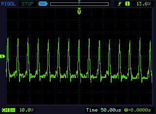
This is… umm… not clean. It’s supposed to be a straight line at 6 V. This looks like someone trying to send covert messages to their spy friend, and pretending it’s a switch-mode power supply.
Indeed, if we look at SyRep’s L4200 schematic, we can clearly see there’s no ripple capacitor on this line. At all. It’s just straight from the inductor. And it’s even negative voltage a lot of the time. Oh the things you could get away with in the age of incandescent lights. The problem is that LEDs react much quicker, so these microsecond spikes will actually cause large power spikes.
The peaks are going over 20 V, so instead of
\[P = \frac{(V-V_f)^2}{R} = \frac{(4.8-3)^2}{100} = 32 \ \text{mW}\]from the resistor, it’s doing \(\frac{(20-3)^2}{100} = 2.89 \ \text{W}\) at peak, which is quite a lot more. With a duty cycle of 10% or so, that’s still 289 mW, or ten times the expected power. It’s also above the 250 mW rating of the resistor. No wonder it was getting warm, melting the plastic and eventually frying the LED chip. I was in shock.
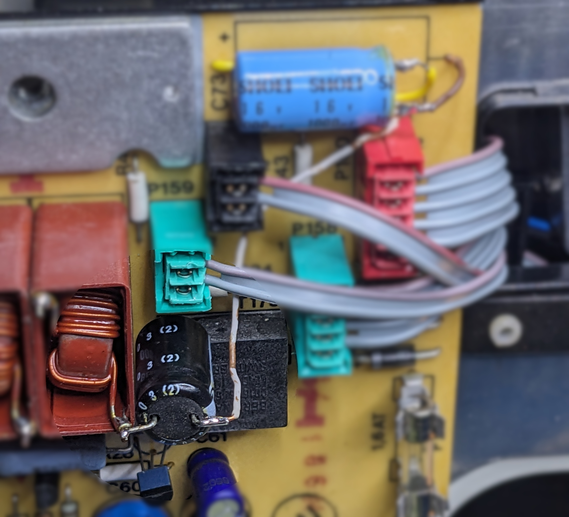
After admitting myself to the local sanatorium for a few days, I decided that a capacitor will keep me sane going forward. So I found a nice spot for it on the L4200 power supply board, right on the lamp inductor (L130). I used ground from the C73 capacitor that smooths the mainboard 5 V line. (Notice that the 6 V light bulbs are driven from the same supply configuration as the 5 V mainboard, and that measures in reality as 4.8 V.)
Now the LEDs aren’t getting warm at all. Win!
Customizing the LED Fixture
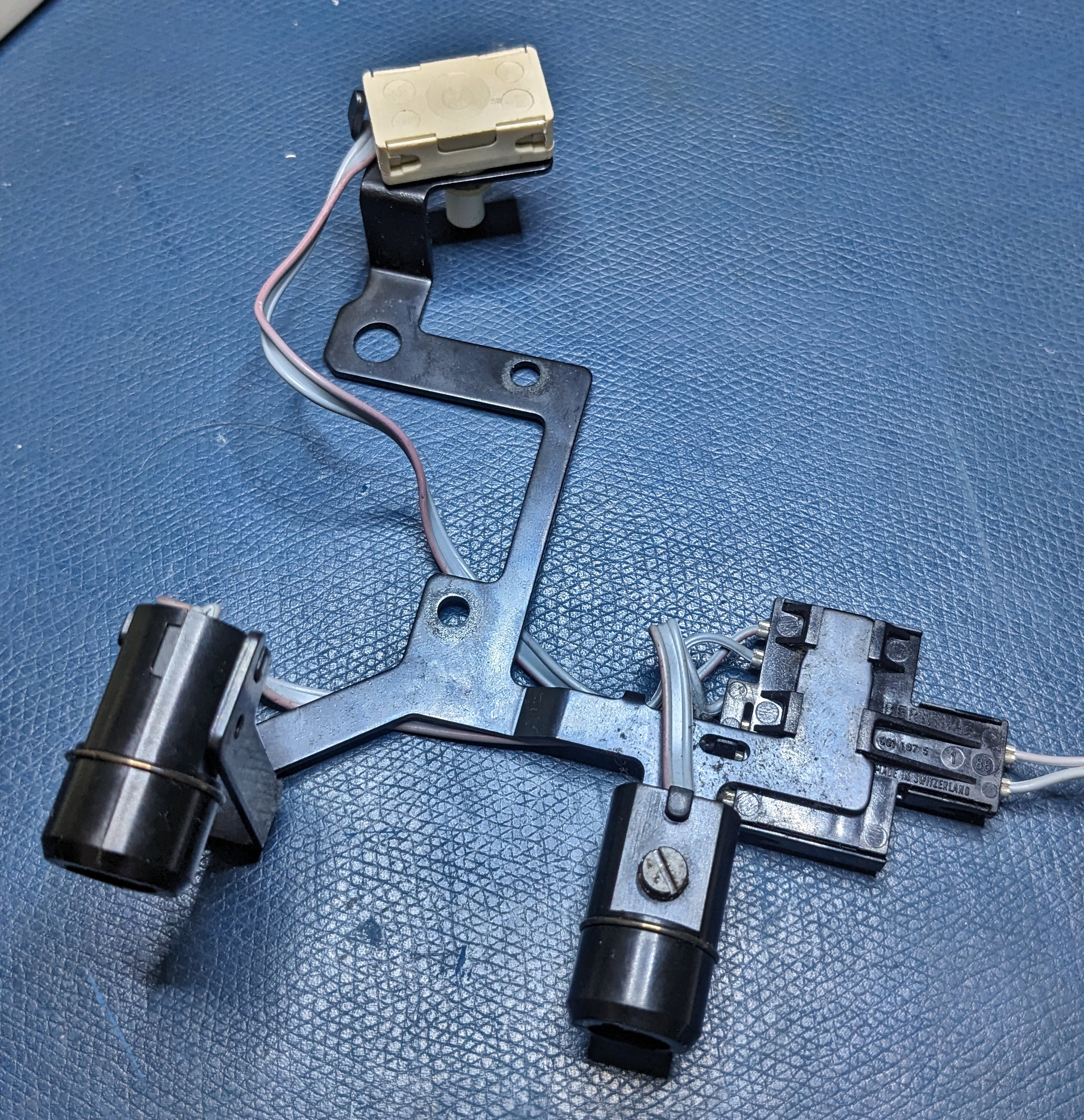
The 1130 is very well made, and the light fixture is no exception. It’s a bracket that is connected directly to the power supply. It contains the connection box, the light switch and the two BA9s sockets. And all that fastened with two screws. It’s very nicely modular.
The BA9s sockets look very cheap and only has a spring contact on one side, so the contact with my own BA9s plugs weren’t great. But more importantly, we can spread out the light a bit more by using the full depth of the machine on the left-hand side. There’s plenty of room for a light bar there.
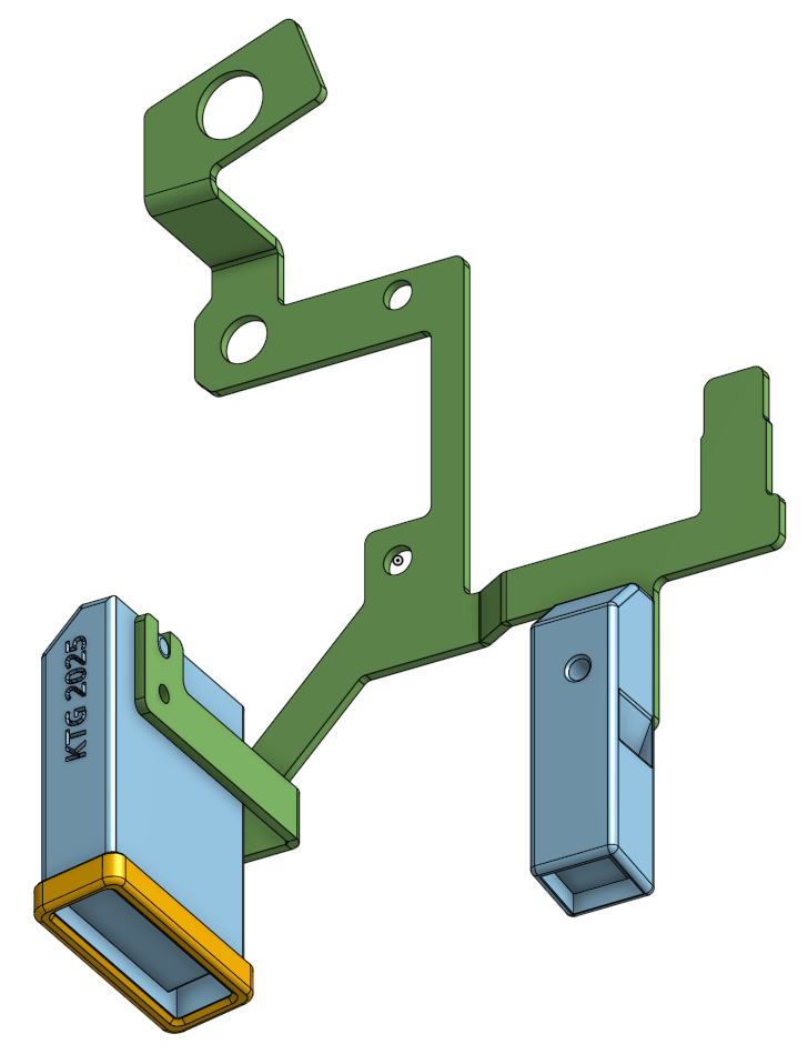
I used OnShape to model the bracket, the available space for the LED fixtures, and then designed something that could hold small circuit boards. I also made a bezel (yellow) to be able to fit a protective front and diffusor. The smaller one in the back already has a diffusor built in to the machine. There’s no space to make anything larger than this there. The slanted channels are for routing the cables away from mechanics and fingers.
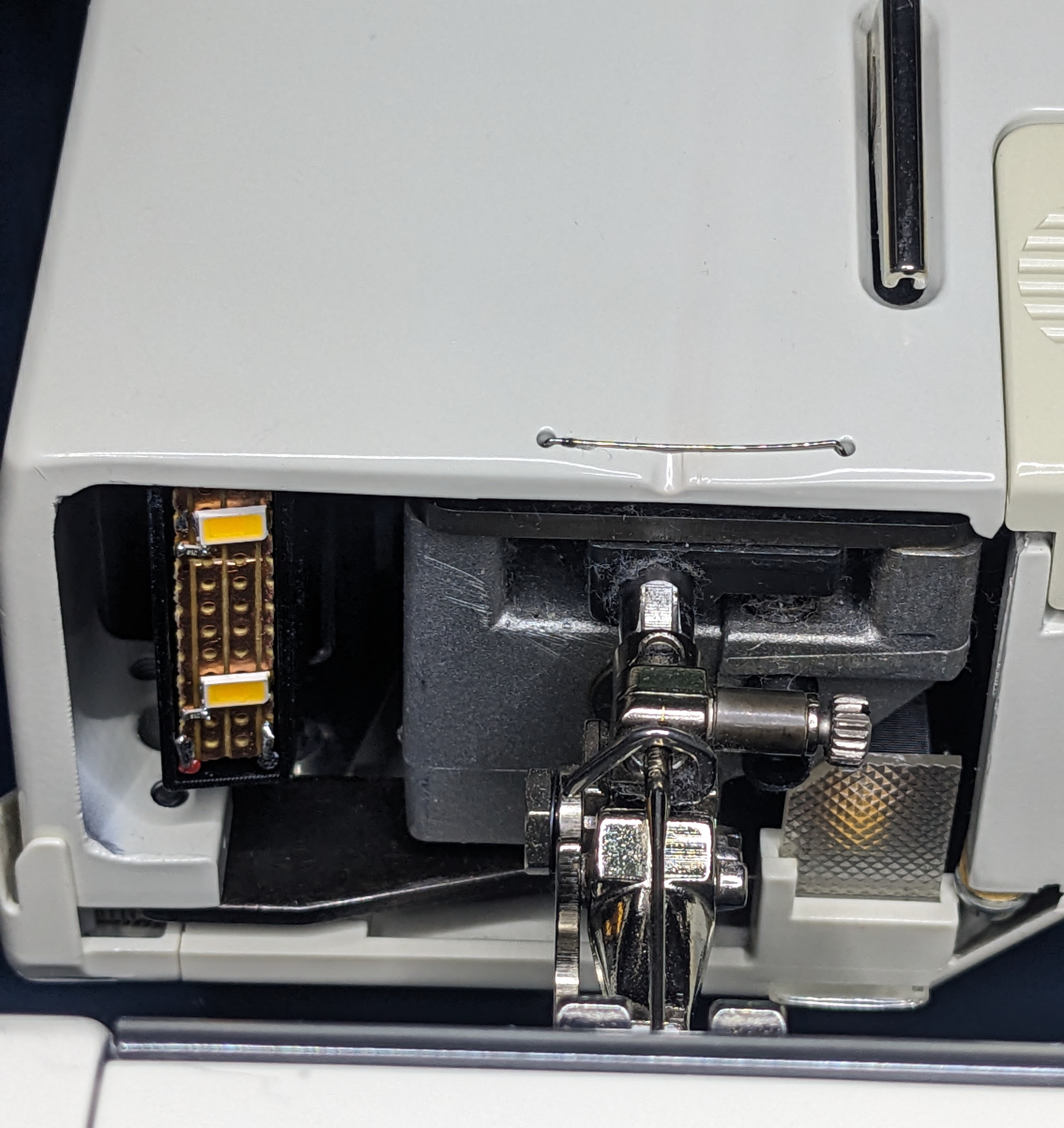
Missing from the final picture of the installed LEDs are the bezel and diffusor.
Lesson learned? Don’t assume that well-built equipment hasn’t been cost optimized. Always check your assumptions and inputs.