This is an overview post of my project to create a replacement for the lost firmware of my Atten AT860D hot air soldering station. At some point, I might dig into more details about the individual parts and the problems they solve. For now, I just want to tell that it exists, and summarize how I made it. (Conversely, if I had more time, I would have written a shorter post.)

The code for this project is available at tommie/at860d-firmware, licensed under GPL-3. It is PIC assembly, using gputils to assemble and link. This makes it a complete FOSS project. The drawback being, you know, it’s PIC assembly.
Anecdote: fifteen years ago, I was working in a company where we used the Hi-Tech PIC C compiler for building various embedded controllers. One of the fun projects included building an I²C-based controller then realizing it almost fit in program memory. I printed the assembly on 16 paper pages, and learned that the ternary operator (if-else-expression) used one instruction more than if I used a conditional assignment statement. Great fun hand-optimizing C! Thank you, Ragnar, and everyone for that time.
With that in mind…
Background
In or around 2018, my hot air soldering station decided to turn its Flash ROM program memory into RAM. I bought it perhaps 3–4 year prior, so it wasn’t that old. My wife had borrowed it (no blame,) and it suddenly wouldn’t work. Odd.
I tried starting it, and it showed garbled characters on the display, but nothing else worked. This suggests the scanning loop for the display worked, as it’s multiplexed and requires a loop. I turned it off and on again (!) and then not even the display worked.
Opening it up, it turns out to be based on the Microchip PIC16F887, which is a run-of-the-mill part, and shouldn’t be prone to just breaking after just a few years. I can’t explain this any other way than the program memory being screwed, so I tried to dump it. It seemed completely blank. Sure, I thought, it might have had code protection enabled, so I couldn’t read it out.
I tried writing a small program to it, but it wouldn’t stick. At that point, the code protection should have been cleared by me issuing an erase command, so that wasn’t it. The program Flash ROM really had turned into volatile RAM. Really strange. Was this some kind of pirate part, or had Microchip actually shipped this? I’ll probably never find out.
Deciding on the Fate of The Device
At this point, a sane person would probably have looked for warranty, talked to the place one bought it at (a European firm,) and asked Atten for a replacement. But, I’m not sane, it seems. I thought I’d make a replacement. How hard could it be? It’s just a heater, an air pump, a display and some switches. As it turns out, the assumptions were true, but the conclusion was a bit foregone.
Anyway, I like reverse-engineering and electronics, so it sounded fun. Plus, there were some issues with the old firmware I wanted to fix:
- My desk light was flickering whenever the device was heating. Not very nice, and this being my electronics lab bench, EMI isn’t great next to my oscilloscope.
- Calibration of the device’s temperature reading is split across the “CAL” mode and the “SET” mode. The idea here is a worker uses the normal mode, a supervisor uses the SET mode, and a technician uses the CAL mode. So the supervisor can tweak calibration (probably the zero-offset,) and the technician/factory can change the coefficient. They could have done it differently, though, gathering all of it under the CAL mode.
- Buzzers and beeps are great if you have a QA supervisor telling you to do things properly. If you’re soldering at 9pm in an apartment, not so much. The buttons are tactile and audible without the buzzer.
- The knob. Oh, the knob. It’s a potentiometer with end-stops. On a device where you can control both air and heat with the same knob.
I don’t know who came up with using a potentiometer instead of a rotary encoder, but the UX sucks. If you’re into production environments, that’s fine, because you’re normally only supposed to change the air flow. But I’m at home, and tweak both the temperature and air. As soon as you touch the knob, it jumps to the now current value. So if you had the knob high, because you wanted a lot of air flow, and now you switch to temperature setting, the next time you move the knob, it will take it up to 400-or-so ℃. Changing it down again is quick, which is the whole point with the knob, but this is an atrocious design. A motorized potentiometer would have been great for this application, and a rotary encoder a good second.
Building Understanding
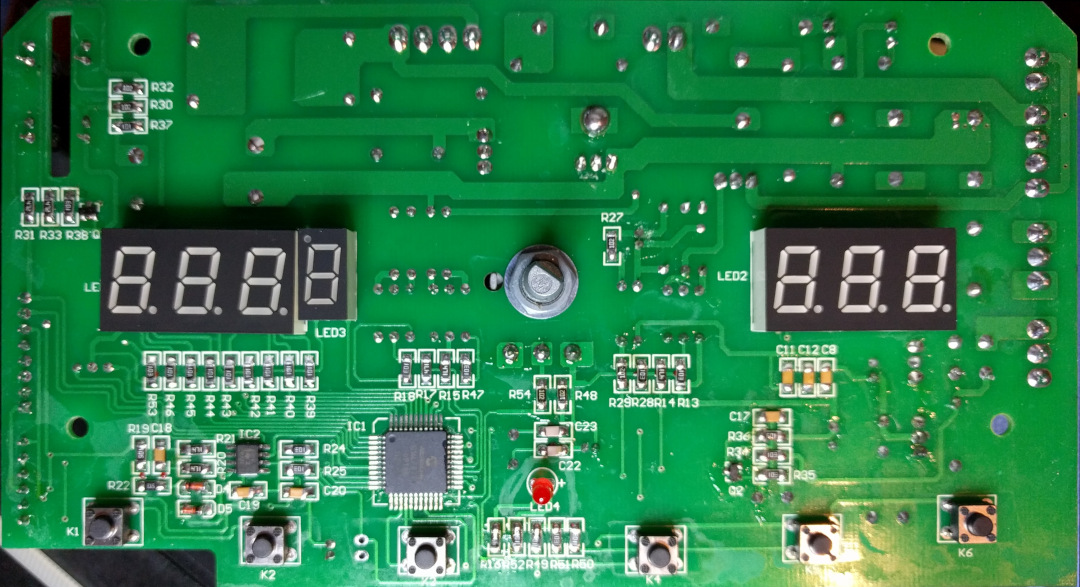
From the initial playing around with the microcontroller, I already knew it was a PIC16F887, so the next question was which IO pins were used for doing what.
There are a couple of different aspects to handle:
- The buttons are in a row-column scanning matrix, including the three buttons on the handle.
- Similarly, the display uses simple segment-digit multiplexing. Note the single-digit smaller display they’ve turned upside down to use the decimal point as a degree-sign. Ingenious.
- There are two analog channels: temperature and the knob.
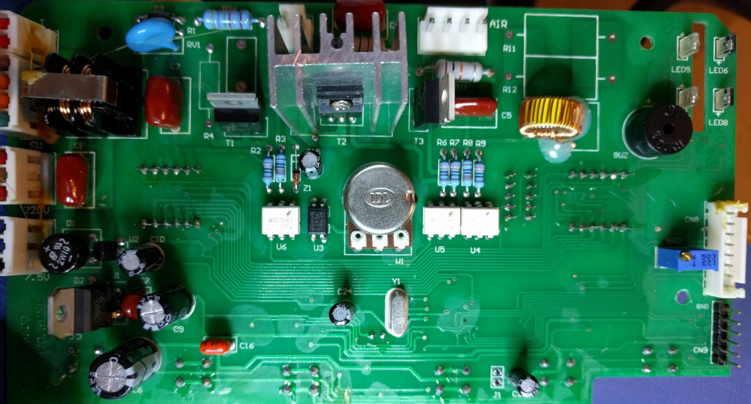
- The heater and air pump each have a triac.
- A third triac is used to override the power switch, so the device can cool down before turning off.
- One input looks for AC zero-crossing, allowing the processor to control the triacs by chopping the AC.
- Related to power control, another input looks for mains voltage, to see if the power switch is on or off. Since the zero-cross detector needs to work even when the power switch is off, there was no choice but to have a dedicated input here.
- The cradle for the handle includes a Reed switch, to know if the device should go into standby.
- One pin is for the buzzer.
- Two pins are used for the photo diodes used to detect the CAL/SET mode key (called the “multi-function card.”)
Nothing fancy, except the cooldown mode overriding the power switch. This all has the microcontroller packed to its brim. Even the ICSP pins used for programming it are occupied (with the button scan outputs.) There is a single pin free (RA1,) or at least I wasn’t able to see it connected to anything.
Since I’ve been doing this once in a while over five years, twice I rediscovered that the temperature amplifier needs a negative voltage supply. Even if it looks like the device can be powered by the 5 V programming header, it reports really high (but not max) temperatures if you don’t have the -5 V!
Two more facts are important for this: the heater uses a MOC3083 opto-coupler, which has zero-cross detection. The air pump, on the other hand, uses a MOC3023, which doesn’t. This means the heater will only turn on when the mains voltage crosses zero. This reduces emitted interference, but also means the heater cannot be “dimmed” using the common chopping of the AC waveform. For a 600 W heating element, this makes sense. Either the heater is on for a half-cycle (i.e. every 10 ms at 50 Hz), or it’s off.
The air pump, OTOH, can be turned on at any point in the AC cycle. (The power switch override also uses a MOC3083, but it’s not time-critical.)
Starting Out With a HAL
Going from understanding the hardware to building something that works is harder. The PIC16F microcontrollers aren’t exactly friendly to work with, with their paged program memory and banked data memory. Lacking multiplication and division also isn’t fun, but there is lots of prior art on the web. I quickly tried SDCC, but its PIC16F-support isn’t really there. So I settled for PIC assembly.
After writing the pin definitions (and their polarity,) I set out to create a HAL (Hardware Abstraction Layer.) The purpose of this code is just to list all the things we can interact with. Explaining the environment to the rest of the code, if you will. First which pin does what, but also setting up scanning the button and display matrices. We don’t want the button on row 1, column 1. We want “the up button.” So this is a bit more complicated than merely “write a bit to a pin,” but it starts there.
The display is driven from a timer interrupt, because it needs to have super-stable timing to avoid flickering. LEDs have very little retention; the moment you turn it off, it will stop glowing. This means that any change (down to probably 100s of microseconds) in how often we light one digit out of the seven will be noticeable. Of course, all the translation from numbers to segments is done in the main loop. As the adage goes:
If everything is a priority, nothing is a priority.
Always run as little code as possible in interrupts. So, for instance the button scanning can happen fully in the main loop. Whether there’s a 1 ms or 1.1 ms delay there doesn’t matter at all. Driving the ADC to read the two channels back-to-back also isn’t timing critical.
Moving Up
Once the absolute basics are done, we need to think about one level higher. I’ll mention two tasks here:
- The triac control, and
- The button press handler.
Without these, the higher-level code would have to do so much it would be cluttered. Finding abstractions and models, as well as dividing and conquering, is what engineering is about.
As mentioned above, the hardware suggests that the heater and air pump have different control modes. The heater uses Zero-Crossing Control (ZCC,) where it’s either on or off an entire half-cycle. Heat changes slowly anyway, so this makes sense.
The air pump uses Phase-Fired Control (PFC,) where the voltage is chopped up every half-cycle. (PFC is a pretty overloaded term, since it usually means Power Factor Correction, but not so here.) A motor that doesn’t receive some energy regularly is likely to stall, or stutter, so this makes some sense to use here.
This means implementing two triac control modes to make this optimal. I wasn’t expecting having to do that. To be fair, the PFC control was fairly simple: when the zero-cross happens, you start a timer, and when it expires, you enable the triac. After a bit more, you disable it again. Because triacs don’t turn off without a zero-cross happening, the disabling isn’t time-critical. We can just wait one timer period (500 µs, in my case.)
Optimizing Zero-Crossing Control for Flicker
ZCC turned out to be more complicated to figure out, because we want the heating to be as smooth as possible. Both because it will make building a closed-loop temperature control easier, but also because of the problem with the flickering desk light. If we turn the heater on at 1 Hz, it will be more noticeable to the human eye, than if we do it at 10 Hz. Say that we can use N half-cycles, enabling the heater for none of them will keep it at zero power, and enabling it for all N half-cycles will keep it at max power.
The question is, what do we do at 50%? The simplest solution is keeping it on for N/2, then keeping it off for the second half. However, this will lead to the lowest possible frequency, with the issue of flickering lights being a larger problem. On the other end, we could keep it on every other half-cycle. This will lead to the highest possible frequency with the same duty-cycle. That’s great.
What about at 42%? It took me a bit of thinking and simulating to realize that the optimal pattern is the binary representation of the reciprocal of the current setting (range [0, N).) That is, a fixed-point representation of 1/x where x goes up to N. I ended up with a Python script that created these rather beautiful flowers, with N=32:
True patterns (unbounded precision)

 0
 1                                  ##
 2    ##                            ##
 3              ##                  ##                  ##
 4    ##            ##              ##              ##
 5          ##          ##          ##          ##          ##
 6    ##        ##        ##        ##        ##        ##
 7        ##      ##        ##      ##      ##        ##      ##
 8    ##    ##      ##      ##      ##      ##      ##      ##
 9      ##      ##    ##      ##    ##    ##      ##    ##      ##
10    ##    ##    ##    ##    ##    ##    ##    ##    ##    ##
11      ##    ##    ##  ##    ##    ##    ##    ##  ##    ##    ##
12    ##  ##    ##  ##    ##  ##    ##    ##  ##    ##  ##    ##
13      ##  ##  ##    ##  ##    ##  ##  ##    ##  ##    ##  ##  ##
14    ##  ##  ##  ##  ##    ##  ##  ##  ##  ##    ##  ##  ##  ##
15      ##  ##  ##  ##  ##  ##  ##  ##  ##  ##  ##  ##  ##  ##  ##
16    ####  ##  ##  ##  ##  ##  ##  ##  ##  ##  ##  ##  ##  ##  ##
17  ####  ##  ##  ##  ##  ####  ##  ##  ##  ####  ##  ##  ##  ##
18    ####  ##  ####  ##  ##  ####  ##  ####  ##  ##  ####  ##  ##
19  ####  ##  ####  ####  ##  ####  ##  ####  ##  ####  ####  ##
20    ####  ####  ####  ####  ####  ##  ####  ####  ####  ####  ##
21  ####  ####  ####  ####  ####  ######  ####  ####  ####  ####
22    ######  ####  ######  ####  ######  ####  ######  ####  ####
23  ####  ######  ######  ######  ######  ######  ######  ######
24    ########  ######  ########  ######  ########  ######  ######
25  ######  ########  ########  ##########  ########  ########  ##
26    ############  ##########  ##########  ##########  ##########
27  ########  ##############  ##############  ##############  ####
28    ####################  ##################  ##################
29  ################  ##############################  ############
30    ############################################################
31  ##############################################################

Approximate patterns (fixed-point arithmetic)

 0
 1                                  ##
 2    ##                            ##
 3              ##                  ##                  ##
 4    ##            ##              ##              ##
 5          ##          ##          ##          ##            ##
 6  ##          ##        ##        ##        ##        ##
 7        ##      ##      ##        ##      ##        ##      ##
 8    ##    ##      ##      ##      ##      ##      ##      ##
 9        ##    ##      ##    ##    ##      ##    ##      ##    ##
10    ##    ##    ##    ##    ##    ##    ##    ##    ##      ##
11      ##    ##    ##    ##    ##  ##    ##    ##    ##    ##  ##
12    ##  ##    ##    ##  ##    ##  ##    ##  ##    ##    ##  ##
13      ##  ##  ##    ##  ##    ##  ##  ##    ##  ##    ##  ##  ##
14    ##  ##  ##    ##  ##  ##  ##  ##  ##    ##  ##  ##  ##    ##
15  ##  ##  ##  ##  ##    ##  ##  ####  ##  ##  ##    ##  ##  ##
16    ##  ##  ##  ##  ##  ##  ##  ####  ##  ##  ##  ##  ##  ##  ##
17  ##  ##  ##  ##  ####  ##  ##  ####  ##  ##  ##  ####  ##  ##
18    ##  ####  ##  ##  ####  ##  ####  ##  ####  ##  ##  ####  ##
19  ####  ##  ####  ####  ##  ####  ##  ####  ##  ####  ####  ##
20  ##  ####  ####  ####  ####  ##  ##  ####  ####  ####  ####  ##
21  ##  ####  ####  ####  ####  ######  ####  ####  ####  ####  ##
22  ##  ######  ######  ####  ####  ####  ####  ######  ######  ##
23  ##  ######  ######  ####  ##########  ####  ######  ######  ##
24  ####  ########  ########  ####  ####  ########  ########  ####
25  ####  ########  ########  ##########  ########  ########  ####
26  ####  ########  ########  ##########  ########  ########  ####
27  ##############  ##############  ########  ################  ##
28  ##############  ########################  ################  ##
29  ##############  ########################  ################  ##
30  ##############################  ##############################
31  ##############################################################

Pattern diff

 0
 1
 2
 3
 4
 5                              -+
 6  +-
 7             +-
 8
 9    -+     -+        -+     -+
10                              -+
11            -+ -+         -+ -+
12          -+   -+           -+
13
14         -+-+         -+       -+
15  +         -+-+-+        -+-+-+-
16    -+-+-+-+-+-+-+
17   -+-+-+-+   -+-+     -+-+
18    -+   -+-+   -+   -+     -+
19
20  +- +- +- +- +-
21   -+ -+ -+ -+ -+  -+ -+ -+ -+ -+
22  +-  +- + - +- +-            +-
23   -+  -+  -+ - +      -+  -+  -+
24  + -  + - +  - +-           +-
25    -+   -+   -+    -+   -+   -+
26  + -         -+    -+   - +  -
27      +  -    +  -            +-
28  +      -   +        -+       -
29         -+           -   +    -
30  +              -
31
(Actually, I rotated the bit-string by half the width, just to get the main “petal” in the middle. :) From the difference pattern, we can see that most differences are single bits shifting one position (the “+-“ sequences,) which seems fine.
The resulting code is simply a lookup table from current setting to this precomputed pattern string. Because it ended up a simple fixed-point computation, we can even let the gpasm assembler create the table from an expression. Yes, I spent some time on that. Anyway, I think it turned out elegantly enough that it was worth it!
Since I don’t have the original firmware, I can’t tell how this differs from Atten’s approach.
Button Presses, Holding, and Auto-Repeat
A much easier problem is dealing with buttons. Once the HAL identifies that a button is (de)pressed, we still need more processing before it’s useful. First of all, we need a debouncer, because all hardware buttons jump a little (10–100 ms) when you click them. If we just detect transitions, we’d easily have glitches, registering multiple presses when there were only one, which suck for UX. Second, we’ll need to see if a button is being long-pressed/held for some functions, like storing a preset. Third, we’ll need auto-repeat for up/down to change temperature rapidly.
There are many ways of doing debouncing:
- If you have buttons directly wired to the microcontroller, you can use a low-pass filter in hardware.
- You could implement a low-pass filter in software. E.g. using a running average.
- You could implement a dead period where you ignore transitions for a while after a first. A temporal hysteresis, one might say. One way would be starting a timer on the first transition, and not care about the input until that timer expires.
- You could implement a dead period where you ignore quickly occurring transitions. One way would be restarting a timer every time a transition happens, and only register the press once the timer expires.
Option two is simple, but not easy to reason about. The third option can react quickly to button changes, but the fourth option integrates better with long-press detection. We can’t register a quick press until we know it’s not a long-press, so we’ll have to wait a long time anyway.
We can start a timer, restarting it on every transition. When the timer expires, if the button is not pressed at that time, it was a normal short-press. If it is still pressed, we start a new timer, and when that expires, if the button is still pressed, it was a long-press. Adding auto-repeat is then a question of saying that when some buttons are long-pressed, they repeatedly generate short-press events. The up/down buttons auto-repeat, but the preset selection buttons do not.
On top of that, we need accelerating repeats, or you’ll go postal from waiting going from 200 ℃ to 500 ℃. So every time there’s a repeat, we shorten the delay until the next repeat, down to a minimum. All of these timing and numbers depend on what feels good. I chose values that felt natural to me.
High-Level Modes
The more building blocks we have, the more useful it is to think about tying them together. We don’t yet have a closed-loop temperature control, but we should be able to control the heating element and air pump directly. We need an app layer that ties together all the individual parts into a product. What some would call the look and feel, or the skin. The things you write about in the user manual. Something that has a flow chart showing you the states you can go into using buttons and knobs.
For me, this started out with the frontpanel module, where the idea was to tie together buttons, display and states.
It was meant to be the “view” layer in my model-view-controller.
However, once I implemented multiple modes (like cooldown and self-test,) this module became the “normal mode” module instead.
Calling it front panel is selling its duties a bit short.
It dictates how the display is used and what inputs do at each point in time. Since I didn’t have a serial port, it also served as the debugging tool, displaying integers from various places in memory. This really is the highest level of the application, and with it in place, we can display temperature, make the heater so hot it burns itself out, and other fun things.
My main point is that I went directly from low-level hardware drivers to the top. What happens in-between is easier to work on once we have both of those ends established. On the one side; the physical environment, on the other; the product.
As time progressed, I added more modes that could take control of the device.
- A self-test mode runs on start, to check that no buttons are stuck, that the zero-cross detector finds mains voltage, that the ADC is sensible, etc. Whatever invariants I could come up with to test.
- A cool-down mode (like the original) which allows the device to keep running the air pump until temperature is low enough to be safe(er.)
- A standby mode (like the original) which disables the heater if the handle is in the cradle, and disables the air pump when below a safe(er) temperature.
- A calibration mode that allows you to set temperature constant and coefficient.
- Fault modes (like the original) which disables everything if the temperature sensor or heater seem wonky.
By the way, the 600 W heating element could probably burn itself out if there’s no airflow, so I was careful not to screw that up. There was a lock-out so the heating element wouldn’t turn on if there the air pump was off. I was also mostly testing the device without mains connected, and when I did, I used a variac to run it at 70 V instead of 240 V.
Temperature Control and Background Work
The most obvious mid-level process is the closed-loop temperature control. I’ll get back to that shortly, but let’s quickly discuss some others.
Another important process is the temperature unit conversion, from raw ADC values to degrees Celsius (in my case.) We also need to be able to write current settings to EEPROM, but we need to sequence that byte-by-byte in the PIC microcontroller. Since the code is event-based and non-blocking, we need to wait for writing to complete before moving onto the next byte. The ADC should do multi sampling, since that’s general best-practice. Fault detection is something that runs in the background, and the other modules use the information to do lock-outs for safety.
Lastly, there’s the watchdog timer (WDT,) which I think is extremely important in a device that can kill its own components if the software stops working. It quite literally only cares about turning off the heater and telling the user that stuff’s broken.
As for temperature control, the obvious choice is a PID controller. Since the PIC microcontroller doesn’t have integer multiplication, and certainly nothing about floating point, we need to keep it simple. There are other PIC microcontrollers with PID hardware, which is cool. It seemed logical to do the same in software, since it was using integers, and designed by people who know more than I do. I could get away with 16-bit integers, using them as fixed-point numbers, so I did. After a bit of tuning, it is now smooth. It overshoots by 15–20 ℃, but so does my normal soldering station. It heats up to 270 ℃ in ten seconds or so, though.
One noteworthy gotcha was that I had to reset the accumulator (I-value) whenever the user changes temperature. This allowed me to keep a fairly high I-coefficient without making the control loop feel sluggish. It’s only used for a couple of degrees around the set-point anyway. I’m sure people who do this every day do it without thinking. Or perhaps just scale it down? The PIC hardware implementation has no special support for discontinuous set-values.
What a Knob
On top of the ADC, the knob is surprisingly complex to read. It has hysteresis to avoid glitches due to ADC noise. It needs to switch between controlling air flow and temperature. It needs to rescale values to the two different value ranges. Then I made it even more complex.
At some point, I was thinking of ignoring the knob, or replacing it with a rotary encoder. But I ended up writing code for the knob, while changing its behavior a bit. Instead of directly jumping to a new value, it requires you to pass the previous value first. Say the knob was set high, while controlling the air flow, and the temperature was set fairly low. You press the heat button to make it control temperature instead. The knob will be dead until you turn it close to what the temperature already is. At that point, you can change it up or down rapidly, as you would with the original firmware.
It might be a bit of a gotcha if you’re unused to it, but to me it feels better knowing I can turn the knob however I want without a sudden jump in values.
Code Structure and Operating System
I’ve talked about the modules, as if “a module” is an obvious thing. This is PIC assembler, so it’s not.
What’s a good code structure for a small project like this (it’s 4,500 sLOC)? Early on, I decided I wanted something modular, and not having to plumb things manually. Inspired by Aspect-Oriented Programming. Each module should be able to place code in the idle loop, without me having to write it into the idle loop. Same with initialization code.
What I did was let each module be an included file, where sections of it had preprocessor guards.
Here is an abbreviated example from airpump.inc:
    ifdef module_airpump
#undefine module_airpump
    endif
#define module_airpump
    ifndef module_triac_pfc
    error "triac_pfc module is a dependency of airpump"
    endif

    ifdef section_udata
airpump_value res 1
airpump_ratio res 1
    endif ; section_udata

    ifdef section_code
airpump_output  macro   file, bit
    movinvbit           file, bit, PORTE, 1
    endm

airpump_idle    macro
    local   mend

    ; ...
mend:
    endm
    endif ; section_code

    ifdef section_init
    selbank PORTE
    bsf     PORTE, 1
    endif ; section_init

    ifdef section_idle
    airpump_idle
    endif ; section_idle
The first part checks that modules are included in dependency order.
The section_udata reserves uninitialized data in RAM.
The section_code contains macros and functions for general code.
The section_init and section_idle adds code directly to these sections.
(In many places, I place code inside macros even if only used once, because it allows using local labels.)
Then I list all the module files in modules.inc, in dependency order:
    ;; Algorithms
    include "stdlib.inc"
    include "fixedp.inc"
    include "pid.inc"

    ; ...

    ;; Tasks using the timer1/int ISRs
    ;; (Timer1 is synchronized to zero-crossings.)
    include "triac_pfc.inc"
    ; ...
    include "airpump.inc"
Finally, the main assembly file includes the modules.inc file multiple times:
#define section_udata
    include "modules.inc"
#undefine section_udata

    ; ...

start:
#define section_init
    include "modules.inc"
#undefine section_init
There are some issues with modules that use “callbacks,” since it creates a circular dependency.
E.g. the timer module should use one of those define-include-undefine blocks, but if I do that, it’s a recursive inclusion of modules.inc, and it was untidy.
On the one hand, modules need to read the current timer value, but they also need to be invoked by the timer interrupt routine.
I could place the code in the main assembler file, like the other to avoid the recursion.
But, alas, nothing is ever finished.
Also, the listing file the linker produces is not the prettiest, because each module is output several times, but it was a simple modular solution.
I created the DiOS project (for Dispatcher OS) to extend the idea of modularity in embedded development. It too uses define-include-undefine (for now,) but it has a code generator, making it plausible to improve that aspect. It adds event dispatching, which avoids the issue with the cyclic dependencies by letting the code generator gather all the callbacks.
Conclusions and Discussion
I’m very happy to once again have a hot air soldering station working again, for my next project (a universal I/O interface for interacting with up to 15 V lines.) The code seems stable, but it’s only running on one device, and not very often, so who knows.
It’s PIC assembler, baby.
Let’s summarize problems I’ve sweated over, and lessons learned:
- Firstly, I had no PIC ICSP programmer, so I built one from an Arduino clone and some transistors. This was one inspiration for my universal I/O project. PIC16F devices require 13 V programming voltage (since the programming pins are also used for I/O.)
- Dealing with timer expiration comparisons on a limited device is fun: comparing unsigned values as signed when you know their range works. The trick is to simply treat them as signed values, and look at the two’s complement sign, not the carry bit. Assuming you can guarantee they are never more than half the value range apart from each other.
- The default PIC16F ADC prescaler setting is too fast for the 20 MHz the board is running it at, causing weird stair-like behavior in values. It looked like it kind-of worked, but would skip some values. Check your prescaler, and compare against the data sheet!
- If your temperature reading doesn’t change while heating the sensor, you may have forgotten to power the amplifier. Don’t be lazy with your power supply setup.
- The zero-cross control of the triac was fun, but before I realized the whole reciprocal thing, it was a lot of writing bit patterns on papers and trying to figure it out.
- There are good ways to control a heating element, and bad ways. In regards to interference with my desk light, my way is better than the original.
- Debugging without a serial port is no fun. Next time, I’d create a 1-wire protocol if needed, just to be able to get a stream of data out of it. Since I’m not using Microchip’s MPLAB, the in-circuit debugging wasn’t an option, even if the ICSP pins had been unused.
- Fixed-point multiplication can be done with lower RAM usage if you keep shifting away bits you won’t need, while doing the multiplication. Once you’ve shifted away the difference between the number of output and input fraction bits, you continue multiplication as normal. So if you want a 12.4 output, you can perform 12.4 × 0.4 inside 16 bits, because four of the eight fraction bits would be rounded away at the end anyway.
- Trying to build a PID controller with an ADC that outputs bad data is a recipe for bad sleep.
- The Microchip PID simplification is very nice, and works well in software too.
- The air pump was making audible pulsating sounds, because the timer used for PFC was not synchronized to the AC cycle. The 500 µs timer period, together with the 10 ms mains half-period created an interference signal that was really annoying. Switching the zero-cross detector to a timer that was synchronized to the AC solved this. One of those fixes that makes you smile, because it’s so tangible.
- The standard advice of turning it off-and-on again is terrible if your program memory isn’t persistent.
- I haven’t been able to find anyone else seeing a PIC microcontroller turn into mush, or another bricked AT860D.
- Controlling air flow is actually the wrong metric. What you really care about is the power you output. So ideally, you’d control temperature and power. The easiest interpretation is that you want to directly control the heater, and the air pump depends on the temperature. Since the air pump is noisy and only has so many quantized levels of operation, I’m not sure that simple interpretation would work in this case. More likely, you’d have to work with power average over longer time periods, like seconds.
- Atten? Yeah, I dunno. It might have been them, or Microchip, or bad luck with neutrinos.
- Without banksel optimizations, the program memory is full, except for 60 instructions, out of 8,192. Luckily, I had no need for Fahrenheit…
Thank you for your attention.