Update: rtl_433 has merged the patch. See the updated discussion below.
Our landlord has the same garage door opener as us, but only has one remote. He’s starting to be worried this failing will cause DoS. He’s right. I had already looked into this when the garage door opener that’s supposed to be built into my car didn’t work with our opener, a Feroso Basic 60. It obviously uses rolling code, but is not listed as supported under Homelink. The biggest protocol in this space is KeeLoq, and it uses a “manufacturer key” as part of the shared secret. This means remotes cannot be used across manufacturers, even if there’s a learn mode. Sigh
Anyway, he had bought a bunch of key fobs from China, and none of them worked.
Neither of them supported rolling codes, so that’s not unexpected, I thought.
But, now I need to sniff the protocol to confirm, so I can recommend what to buy instead…
This led me into sniffing the 433 MHz band with a cheap receiver module (SRX-882) and an Arduino (actually a Bluepill.)
I wrote the srx882.ino many years ago to reverse a key fob for a gate remote.
Of course, this derailed, because there was a much more pronounced speaker in the aether; my weather station sensor. Yes, yes, the key fob most likely uses KeeLoq. That’s no fun.
Update 2 It turns out the garage door opener remote is compatible with one found at Hornbach, though it’s meant for a different opener. When I searched for the circuit board model number, I only got one hit on the internet: Hornbach. The gamble paid off. My landlord is happy to have spare remotes again.
Let’s reverse engineer the sensor instead!
Periods of Silence
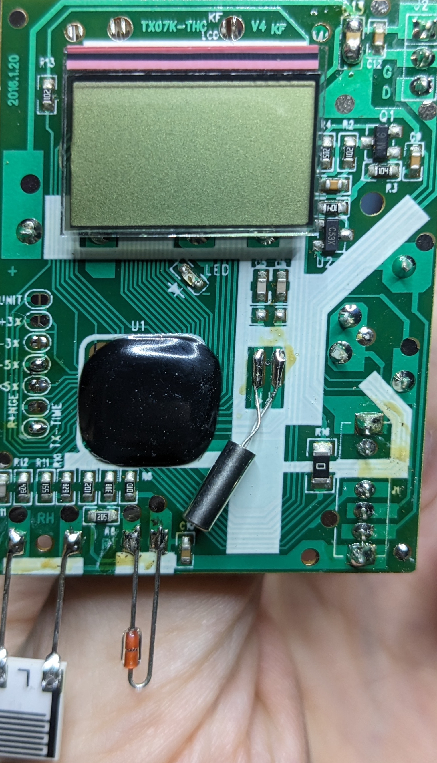
The device in question is a TX07K-THC V4.
After running the Arduino and logging some serial data, it was time to dig in. With patterns such as
100010000000100010000000100010001000100010000000100010001000100010000000100010000000100010000000100000001000100010001000000010001000000010001000100010001000000010001000000010000000100010001000100010001000100000001
it was fairly easy to see this is “Morse code.” Seems this is sometimes called pulse distance modulation (PDM), but I haven’t been able to find a proper source for that name. Find the ones and count the number of zeros following them.
We are left with
0101 0000 1000 0101 0110 0010 1000 0101 1000 0001
and we note this is 40 bits, which seems like a round enough number to be correct. More compactly, it’s 0x5085628541 if interpreted as a big-endian integer. Of course, this doesn’t tell us much about the data.
By the way, this is a useful command to log serial data using socat:
socat -b64 -u OPEN:/dev/ttyACM0,b115200,icanon=1,igncr=0,icrnl=0 STDOUT | ts 'T%s' >cap-$(date +'%Y%m%d')-1.txt
Going Fishing
The next step is to collect a bunch of data and keep track of what the sensor tells us the correct temperature and humidity readings are.
5004636491
50a4634491
5004634501
50d4632501
5024631501
50d4632501
5024631501
50d4632501
50c4632511
5064630511
50a462e511
509662d511
507662b521
50c662c511
502662a521
50d6629521
50e6629511
50d6629521
50e6627521
50b6626521
50e6627521
5046625521
5096623521
5054623521
These are consecutive readings, with duplicates removed. I started this process with not enough data, which had me stumped for a while, because 4 and 6 kept showing up as magic numbers. They looked like constants, and they drew me into their world. I shouldn’t have let that happen. Anyway, we know there’s going to be a temperature and humidity in there. Looking at 434 MHz RF Protocol Descriptions for Wireless Weather Sensors, it also looks like channel, “ID” and battery-low are common in these protocols. Indeed, my receiver has an indicator for low battery. Sadly, none of the formats seem like a perfect match for the data being sent.
To explain the quotes I used above, the ID seems to be some discriminant used to reduce the likelihood of two sensors on the same channel interfering. The receiver will latch on to the ID of the first sensor it receives, and ignore others. The ID typically changes anytime you restart the sensor, which is why it doesn’t feel like an identifier to me. So now we know things to look out for.
Channel
The easiest field to identify is the channel. I had it set to 1 in the excerpt above, so it seems the last nibble is channel. This is unlike many sensors listed in the document above, which has the channel in the early bits. The same goes for devices in RTL 433.
It’s easy enough to verify. Setting the sensor to channel 2 changes the last nibble to 3, so there’s that. Wait, what?!
What if I set it to channel 3. It still outputs 3. Umm, what?!
OK, this was a frustrating time, and took a while before I challenged the right assumption. While looking at the checksum (more on that later,) it seemed the checksum changed even if the last nibble didn’t… Turns out my PDM decoder was misinterpreting the last bit. After fixing that, the channel nibble worked out.
Splitting Fields
What about the other values? If we stare long enough at the list of digits, we can see that some columns change more often than others. Those are probably the LSDs of some integer. Working that out, we seem to have groups like
507 6615 53 1
But actually, that fourth digit (six) seems to switch from four to six without affecting the next digit.
500 4 636 49 1
50a 4 634 49 1
500 4 634 50 1
50d 4 632 50 1
502 4 631 50 1
50d 4 632 50 1
502 4 631 50 1
50d 4 632 50 1
50c 4 632 51 1
506 4 630 51 1
50a 4 62e 51 1
509 6 62d 51 1
507 6 62b 52 1
50c 6 62c 51 1
502 6 62a 52 1
50d 6 629 52 1
50e 6 629 51 1
50d 6 629 52 1
50e 6 627 52 1
50b 6 626 52 1
50e 6 627 52 1
504 6 625 52 1
509 6 623 52 1
505 4 623 52 1
Some observations:
- First: only last digit changes, and it jumps all over the place.
- Second: it seems very “binary”, so perhaps that’s a bit mask with flags.
- Third: very smooth ramping (compared to the first group.) 12-bits suggests temperature, if we compare to other sensor protocols, and the fact the display uses one decimal place in Celsius.
- Fourth: very stable around 0x50. Perhaps humidity. The jump from 0x49 to 0x50 makes it look like BCD. Hmm, if they use BCD for humidity, do they do the same for temperature? Nope, we see hexadecimal digits there. Wow, really?
- Fifth: already identified as channel.
Humidity
Comparing the fourth to what the display shows confirms this is indeed relative humidity, in percent, using BCD.
Temperature
Let’s look at a temperature: 0x62d
That’s 1,581 in decimal. Certainly not Celsius or a decimal fraction thereof. Tough luck. I ended up plotting these values against the display temperature in a spreadsheet:
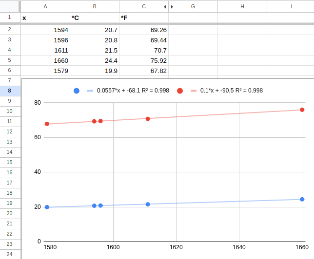
Using linear regression gave a value like temp = 0.0557x - 68.1, which looks so odd that it can’t be right.
No one will define an integer protocol with that coefficient.
When I converted the values to Fahrenheit, it became tempf = 0.1x - 90.5, which seemed much more likely.
So I concluded the temperature is a 12-bit integer in deci-Fahrenheit and offset 90 ℉, observing that R2 was only 0.998 in the plot.
Device Generation / ID
While recording RF (for a day or two,) I also removed the sensor battery a couple of times. When I plugged it back in, the first two digits changed, but remained static. This suggested it’s the device ID discriminant used to make devices “sticky” to receivers on a channel.
So that leaves only two digits unaccounted for; the third and fourth. In reality, I had already assumed the third to be a checksum, since it was changing so randomly. Once you have enough data, you can start to compare packets where only one bit differs:
47 2 6 608 54 1
47 7 6 609 54 1
and noting that the temperature changing by one unit makes the third digit jump five. We’ll come back to that shortly.
Flags
For the fourth nibble, I could see values 4, 5 and 6, though 5 is rare. In all of these, bit 3 is set (counting from LSb as bit 1.) I replaced the battery with a bench power supply and changed the voltage. If the voltage is below 2.5 V, bit 3 comes on. OK, so that’s low-battery. Since the data often switches between 4 and 6 without 5, it’s unlikely the least significant bit has anything to do with battery level. Though, perhaps the second one does? My power supply couldn’t trigger these bits, so unlikely.
I stopped the investigation since there wasn’t anything obvious on the receiver display indicating the unknown bits were interesting.
Edit The highest bit turns on when the manual transmit button is pressed.
Edit After some more looking at flags, and using a hot air gun to change the temperature, the bottom two flags show the direction of the temperature. Bit 1 is temperature rising and bit 2 is temperature falling. They seem to react quickly (a single unit of change can set it off,) but there is some low-pass filtering going on, because it doesn’t react to all changes. They reset to zero after 25-60 min of no change.
Checksum
This took several hours (spread over three days) to figure out! I just couldn’t stop, though.
Most protocols seem to just sum over bytes or nibbles. Some of them use XOR (a.k.a. sum-mod-2, or parity) instead. Some use a sum, and then invert or 2-complement them.
Many of the protocols in rtl_433 use a CRC or LFSR.
Because the check digit was jumping around a lot, suggesting a reasonably good checksum, I first tried with CRC-4, playing around with the crccheck Python library. That didn’t give any clues. Then I found CRC RevEng which is a CRC reverse-calculator. That didn’t find any matches either. I was stumped!
I wrote the diffat.py program to find pairs of packets that only differ in one bit (ignoring the checksum.)
It was difficult to capture changes in the channel.
There are only channels 1-3, so I couldn’t trigger the upper bits.
In the 12-bit temperature integer, I couldn’t change the temperature enough to affect the highest nibble.
And when the middle nibble changes, the humidity and flags must remain the same to be useful.
That only happens rarely.
The only solution here is to run the sniffer for a long time, and hope for the best.
Running sniffing overnight really helps, because in the morning the values change rapidly, so there’s a high chance something interesting happens where most digits align. After four days, I had a decent amount of data to look at. Currently standing at 1,500 packets, ignoring duplicates. I could find small diffs for most nibbles up to the third nibble.
Differential Analysis
I started writing lists of pairs with diffs in only one or two bits (with the checksum moved separately):
Input     C  Cbits Cdiff

505657592 9  1001
505657593 3  0011  1010
        1

504653531 f  1111
504653533 2  0010  1101
        2

4745f5561 c  1100
4745f5571 d  1101  0001
       1

50465a511 6  0110
50465a551 2  0010  0100
       4

504647481 f  1111
504647581 c  1100  0011
      1

474622521 1  0001
474623521 4  0100  0101
     1

506656501 2  0010
50665e501 c  1100  1110
     8

50464f531 50 9  1001
50465f531 50 6  0110  1111
    1

504653511 50 d  1101
506653511 50 1  0001  1100
  2
I translated the checksum to binary and looked at the diff, i.e. basic Differential cryptanalysis.
For each of the bits above, I had more than one example pair. Without that, I couldn’t know if it was chance or a systematic property. Only showing a subset here, and one example per bit, to keep the blog post a bit shorter.
What stood out was that in the second-to-last nibble, any single-bit change caused the corresponding bit in the checksum to change. This applied to all individual bits, and combinations of them. So it seemed the checksum calculation stopped with that nibble being XORed into it. Again comparing to CRC and LFSR, none of them have this property. CRC does a shift after XORing the data. LFSR XORs with a “generator”, not the input data.
A major insight was that bits in the early nibbles changed the bits in the checksum deterministically. This suggested the checksum was XOR-based, and not a sum. Had it been a sum, we should have occasionally seen a bit “bleed” as a carry was being propagated. Granted, I didn’t have enough samples to say so for sure, but it seemed likely. I also couldn’t find examples of complicated checksums using addition; they’re all simple sums or using shift-XOR.
The further away we go from the second-to-last digit, the more complex the changes are. It’s interesting that the last digit (channel) causes larger changes than the second-to-last. Since I only had very limited data here, I couldn’t get more than three bit transitions there, but all of them looked complex, changing more than one bit.
Moving The Channel
This led to one crucial decision: to assume the channel is actually taken into consideration earlier. So some re-shuffle happens before the data is being sent. The obvious place for it would be where the checksum is, at the third nibble. In previous attempts, I had simple removed the checksum nibble when computing the checksum, but since the sensor CPU is probably 8-bit, it makes sense to fill the half-byte-sized hole with something during checksumming. There aren’t enough “unused” bits in the fourth nibble (flags) for that to be a candidate. I played around with CRC RevEng, but still couldn’t get a match.
For the third-to-last nibble, I didn’t have clean single-bit diffs, but I had a few samples where only bits of the second-to-last nibble also changed:
50560d593 b  1011
50560d693 4  0100  1111
      3

505653501 a  1010
505653601 f  1111  0101
      3

5045bd642 0  0000                0100
5045bd702 7  0111  0011<-0111    0111  0011
      14

5045bf642 a  1010                1110
5045bf702 d  1101  0011<-0111    1101  0011
      14

504650481 8  1000                0000
504650501 3  0011  0011<-1011    0011  0011
      18

50465c491 0  0000                1001
50465c501 a  1010  0011<-1010    1010  0011
      19

5045cc591 b  1011                0010
5045cc601 7  0111                0111  0101
      39

50464b481 6  0110                1110
50464b601 8  1000  2:0110<-1110  1000  0110
      28
Since I could simply XOR-away those changes, I could see what happened at the presumed last iteration of the checksum loop. Again, I could see that the 0x14 diffs didn’t move bits around even for different checksum values, showing once more that it’s XOR, not addition. Removing the other changed bits, the first bit consistently causes 0b0011.
However, if you look at the 0x3 diffs, they’re not consistent! This suggests there’s a bit-by-bit loop happening, and not a nibble-by-nibble (or byte-by-byte and later merge) operation. This got me back on the CRC track. This is what a normal 4-bit CRC looks like:
def crc4(bs: bytes, poly: int, init: int):
    rem = init

    for b in bs:
        rem ^= b
        for i in range(0, 4):
            if rem & 0x08:
                rem = (rem << 1) ^ poly
            else:
                rem <<= 1

    return rem & 0x0F
But we need the XOR with b to happen as the last step.
What if it’s a broken/modified CRC?
I couldn’t test that with CRC RevEng, sadly.
That’s when I wrote crcbf.py to play around.
There was still the question of where the channel should go, but I already had a good guess.
Trying all combinations of polynomial and initial value for 4-bit numbers isn’t exactly taxing.
Check Mate
I moved the XOR b to after the if-statement.
I ran the program and at first it looked very promising!
It spit out poly=3 and init=0, which are very plausible values.
With a 4-bit checksum, I had many false positives before, but this seemed to pass more than 16 samples!
However, there was one packet that failed, out of 20. This is where that PDM decoding bug comes into play again. Even though I had filtered out odd packets (requiring more than one packet out of a burst to be the same,) it couldn’t protect me from screwing up decoding of passing packets. After figuring this out, I finally had an answer to the frickin checksum.
It’s a broken CRC-4 with polynomial 3 and zero initial value:
def crc4ish(bs: bytes, poly=3, init=0):
    rem = init

    for b in bs:
        for i in range(0, 4):
            if rem & 0x08:
                rem = (rem << 1) ^ poly
            else:
                rem <<= 1

        rem ^= b

    return rem & 0x0F
If I run this on my 1,500 captured packets, the ones that pass the 40-bit length check pass the checksum. There isn’t much 433 MHz traffic around me, so it seems plausible there are no collisions that would corrupt them.
RTL 433
Looking through the device database in RTL 433, it seems WEC-2103 is the same device. It’s missing information about the elusive checksum, and low-battery flag. I’ve filed rtl_433/#2661 to discuss adding it.
Update: The checksum is now merged, which means WEC-2103 decoding is enabled by default! The rtl_433 maintainers felt that the code could be rewritten as a CRC-4 with an additional XOR of the last nibble at the end: (It also still requires moving the second-to-last nibble.) I completely agree that’s nicer for maintainability.
Conclusions
The complete decoder (save for the flag bits) is in tempdec.py.
The srx882.ino code had only been used for PWM (0b100 for zero and 0b110 for one) before, but it was nice to see it generalized to PDM.
Identifying fields was fairly painless. Next time, I would/will consider building a sender for the flag bits, and keep staring at how the display changes.
The sensor sends temperature in deci-Fahrenheit, which looks really uncommon. Most (chinese) sensors use deci-Celsius, it seems. Figuring this out using linear regression was a good approach.
I was blinded by the digits 4 and 6 popping up often for too long. It looked like they were field separators. It makes no sense to have field separators in a nibble-based, tightly packed, protocol. I should have thought “these are most-significant digits” earlier.
The checksum was a beast. I think differential analysis is really good for XOR-based checksums. It requires quite a few data points to be able to figure out the order of operation, especially when that order differs from the transmitted data layout. Look for where the smallest changes are, and go from there, backwards.
Perhaps I could have used a transmitter to fake the sensor and just brute-force to see what checksum the receiver would recognize. I’m not actually sure that would have been faster, to be honest, since the receiver is a bit slow, and I’m not sure it would have reacted immediately to new data, even if valid.
Finally, the 0b0011 that showed up for changes to the lowest bit of the third-from-last nibble should have been a hint that this was the CRC polynomial.